CONCAVE EARTH I: THE RECTILINER
creatumejortu.com/la-tierra-es-concava-el-rectilineador
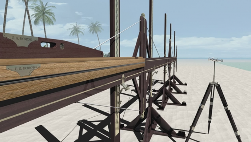
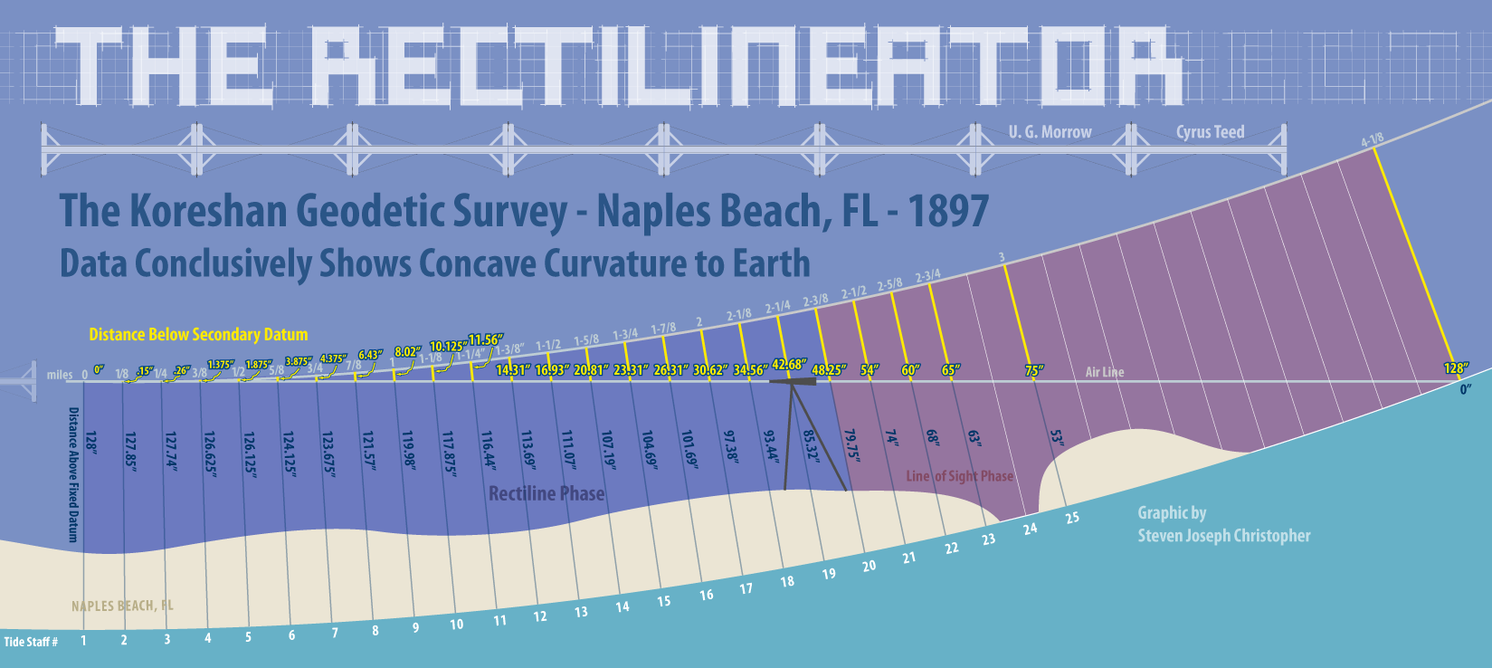
In 1905, engineer Ulysses Grant Morrow and physicist Cyrus Reed Teed wrote the book 'Cellular Cosmogony', claiming that we live inside a concave Earth . To verify these claims, Morrow developed a simple invention called the 'Rectilineator', which was tested in 1897 on the beach at Naples, Florida.
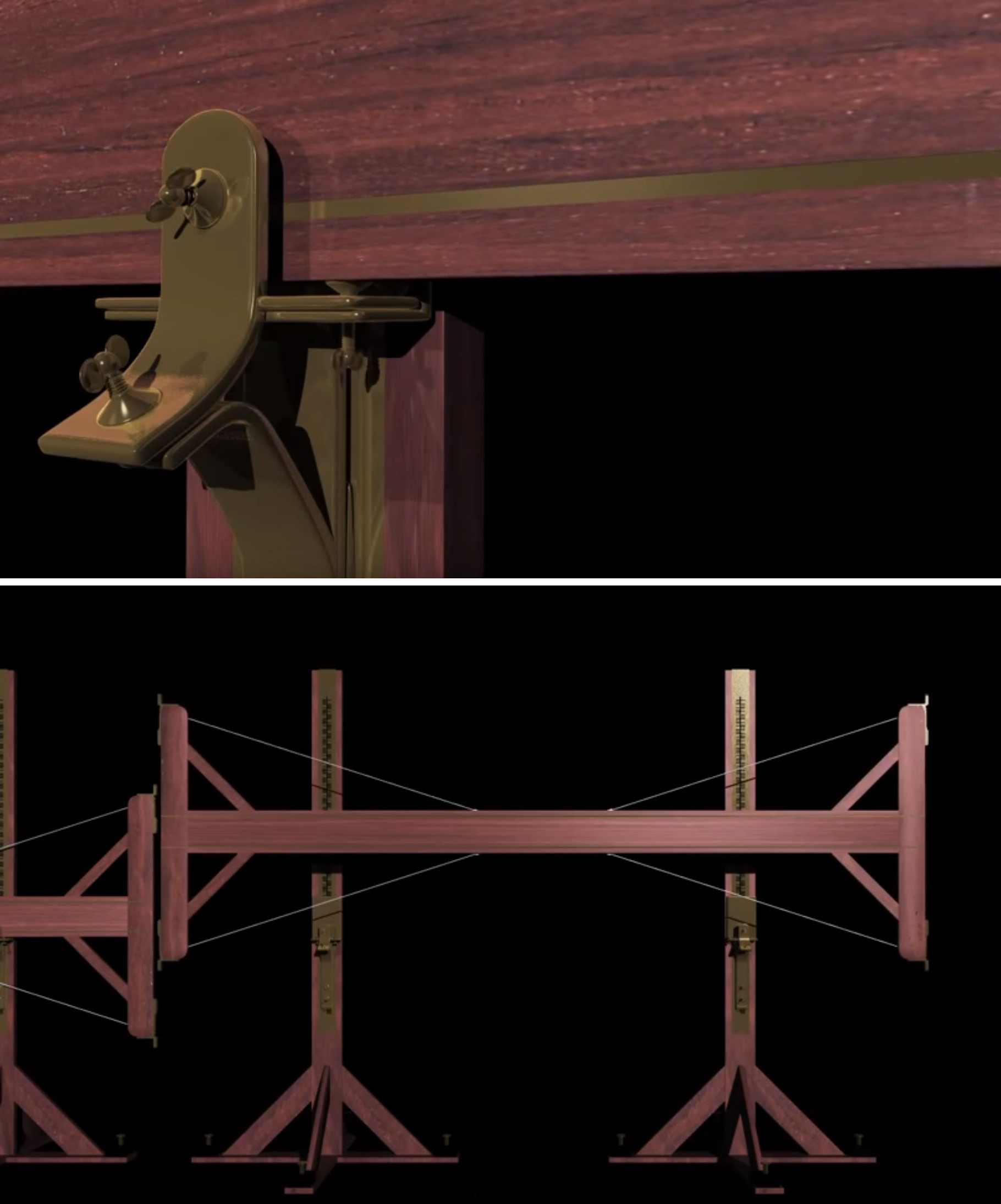
This consisted of a series of 3.5 metre long, 20 cm wide beams of mahogany soaked for 12 years , supported by two upright posts (which Teed calls 'standards') with copper pieces attached which served to rest the beams, and at the same time to fix the height by turning adjustment screws on the front sides of each piece.
«Through flanges on both sides, ingenious screws were fitted to secure adjustments when these were made… each section was supported by two strongly constructed posts, with adjustable castings to receive the horizontal sections between the body of the castings and the adjustable clamping system with clamps and screws . The sections rest on the copper castings… «
At each end of the support were vertical crossbars 1.2 meters long and 13 cm wide, with a different set of copper harnesses mounted at the top and bottom of each crossbar. Steel cables were attached to these copper harnesses, ensuring the assembly was tensioned .
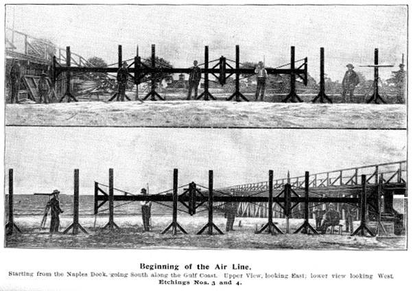
The 3.5-meter supports were erected along 7 km of nearly flat sandy beach in Naples Bay, Florida, facing south, initially parallel to the shoreline. The initial supports were placed before the waterline, so this dry portion of the beach had to be excavated to create a continuous route level with the rest of the beach , which was below water level.
"On the one hand, the air line was to be straight; on the other, the low or bank line was somewhat irregular, since the elevation of the land above the water level varies by an average of 1.2 meters. Excavations were necessary , along with much other work of a similar nature, to remove all obstructions and clear the way for appropriate operations so that there would be no interruptions when the adjustments to the supports began."
They used three leveling devices to ensure the first support was absolutely flat: a plumb line (hung from vertical crossbars), a spirit level, and a geodetic level, which was a 3.5-meter-long vial with mercury in two intermediate sections. At the same time, they checked the bottom bar of the support to ensure it was also level with the horizon. This was done with the utmost care and precision .
"The leveling was a careful, exhausting and successfully executed task, in the presence of all members of the team, and was finally declared perfect at 8:50 in the morning of March 18, 1897."
Once the first supports were leveled, two more were placed in a row, their copper pieces positioned at approximately the same height as the first support. The second post was then placed on these pieces, and the fixing screws were clamped to the copper pieces . The second beam was moved up or down so that it roughly coincided with the horizontal centerline of the first support beam.
Watch Video At: https://youtu.be/EB2-qhfj0fY
The supports were moved within a range of half a centimeter, being adjusted to the ends of the cross arms of both supports. The adjusting screws were turned more or less to raise or lower the horizontal beam, so that the leveling lines of both supports coincided exactly with each other; this leveling was carried out using a microscope . Thus, the second horizontal beam was carefully positioned within a margin of half a millimeter with respect to the copper pieces of the first support, so that the leveling procedure was as perfect as possible .
This millimeter-sized gap was determined by friction tests with thin paper, passing it between the lateral copper pieces. Apparently, the papers were always of the exact same width, as they had been previously measured with a micrometer. Thus, by ensuring the same friction of the paper as it passed between the opposite upper and lower copper pieces of the cross arms, he achieved 100% certainty that both horizontal beams, aligned one after the other, were level with each other, within a margin of error of just half a millimeter .
On page 102 the authors show how the engineers ensured that the cross members were 100% at right angles to the horizontal beams:
«The crossbars of each section must be tested to ensure they are at right angles to the fine leveling line or axis of the apparatus's sections. The inventor himself and expert mechanics devoted four weeks to testing and adjusting the right angles : six series of tests were executed, and each section was inverted, checking the angle on each side of the crossbar, and at each of its ends, right side up and upside down. These six series of checks were repeated more than fifty times with mechanical measuring and reference devices. The finest possible dots and lines were engraved on steel and copper plates, which served as references for the adjustments, using a microscope; in this way, any slight variation in angle could be detected .»
Steel tension cables were used to ensure the vertical crossbars remained at a perfect right angle, while also checking the friction of the paper. Once the second support had been aligned to the millimeter with the first, the two sections were bolted together to prevent any slightest movement . These bolts were very solid in their position, as the authors note:
«…The alignment was fixed in such a way that it was impossible to deviate from it; the bolts holding the copper pieces of each crossbar together were set at right angles, so as not to allow the slightest alteration during the execution of the experiment.»
This procedure was repeated several times until there were no more 3.5-meter sections left to add. The first 3.5-meter section was then moved, fitting it onto the end of the last, alternately turning the horizontal support over with each addition to ensure there was not even the slightest leveling error .
«The method employed to ensure even greater accuracy was to have the apparatus neutralize its own inaccuracies by inverting or turning over each section at each alternate adjustment. This process could correct any errors arising from any inaccuracy in the copper rivets, causing any misalignment a crossbar might exhibit, to within half a millimeter of a right angle, to be corrected when that section was inverted, as any good mechanic knows.»
This procedure was repeated for each of the 3.5-meter sections along 200 and 400 meters, adjusting the horizontal level up or down relative to the last section. Every 200 meters, the height of the horizontal beam was measured relative to the water level below, since the water plane is always level with the land. However, the water had its tides, and their level had to be measured . This was done using an apparatus called a 'caisson,' consisting of a perforated basin to allow the water to remain stable and thus be easily measured. This could be a weak point in the experiment, since the height of the tide marked on the caisson post (3.2 meters) had to be level with the height of the shore post, where the original supports had begun very close to it. This was done by line-of-sight with a telescope . Once the shore stake marking the tide level was at the same level as the tide in the caisson, the stake aligned with the tide level was quickly carried 200 meters further and compared with each of the 25 shore stakes previously aligned, and also with the shore stake that was leveling with the tide at that time, to see if they all matched the level.
If the distance between the waterline and the horizontal support was the same in each 200-meter section, then this would prove that the Earth is flat. If the distance continuously increased, moving away from the Earth, this would prove that the Earth is convex; if the distance decreased, it would prove that it is concave.
The results conclusively demonstrated that the Earth is concave. Even the most skeptical of all, Donald Simanek, agrees that the results appear to be genuine :
Even more remarkable is the fact that the results were consistent with an Earth circumference of 40,000 km (the measurement established by science). Reviewing the data with more modern analysis techniques than those employed by Morrow's team, the data show that the margin of error is a little over 2%.
The fact that the average of the assigned deviations is so small indicates that individual values fluctuate equally above and below the mean. This is an indication that the data are reasonably normal, and the distribution of random errors is not skewed . While individual values fluctuate about 10% around the mean, the deviation from the pooled mean is only about 2%, thanks to the process averaging 24 values. This 2% mean deviation is comparable, as a measure of the goodness of the result, to the standard error margin currently seen in any research article.
For the moment, based on the data alone, this would appear to be a good experiment , with margins of error commensurate with the instruments and methods used.
However, not only was the levelness relative to the waterline measured , but also the angle of two plumb lines on each of the cross arms, the levelness of the beams with a spirit level, the divergence between the air line and the horizontal with a mercury geodetic level, and the space between the forward straight edge and the horizon. Basically, the same method and apparatus were used that made the first support level at the very beginning of the experiment.
Although the level of the supports was tested every 200 meters, the equipment wasn't sensitive enough to give accurate readings during the initial tests, so the readings were given at 1.5 km, 3 km, and 4 km. Here, all the results confirmed that the Earth must be concave, with a circumference very close to 40,000 km .
«The bubble had shifted slightly (towards the North, or rear section of the apparatus). From the first point where the deviation became apparent to the end of the line, the angle increased proportionally to the distance traveled . This was also corroborated by the position of the plumb line and the observed increase in the angle between the straight edges and the horizon, always converging towards the South.»
You might think, 'Well, the supports were in the sand underwater; they might slip and give crooked results.' However, the results were very consistent, showing no irregularities whatsoever , such as showing a convex Earth one time and a concave one the next, for example. They even addressed this potential drawback by painstakingly retracing the same line back 600 metres and getting the same results. A further 70-metre retraction, also described in more detail on page 103/4, gave exactly the same result as the original line to within 0.00254 millimetres!
«Some suppose that slippage must have played an important role in the lowering of the erected line; if so, why should the line drop 3.8 millimeters in the first 200 meters, and 15 centimeters for the 200-meter section between the 19th and 20th tide posts? If improper settlement caused the lowering, it would be apparent by retracing the same line . We
retraced the same line a distance of 600 meters to determine whether there was any deviation. The fact that the horizontal axis of the apparatus on which the survey line is projected returned to the same points recorded certainly proves that slippage factors, if they existed, were absolutely neutralized, because the apparatus never deviated from a true and directed rectilinear course. Let those who raise such objections explain how the exact and definite ratio was obtained if we had not laid out a straight line from the beginning of the survey.
(Page 103/4) […] 70 meters were measured; a pole was fixed at the beginning, with a copper plate bearing a fine line coinciding with the horizontal line of the apparatus. 19 forward adjustments were made, and they returned to that direction; at the last return adjustment, the section was found to be exactly in the same place as at the beginning, with the line accurately adjusted over the fine line of the copper plate. The results were obtained by observations with the microscope; the apparatus returns to the same point, after traversing the space of 140 meters, with a margin of error of 0.00254 millimeters .”

Another possible problem could be the material. Although the supports were made from mahogany soaked for 12 years, does wood or copper expand or contract with slight temperature changes from day to day, or with the possible absorption of seawater? To this end, it must be said that the supports were so meticulously manufactured, as we have already seen, that this probability is very remote; furthermore, the results would again not be as consistent as they were . The authors responded to this potential problem as follows:
«One source of inaccuracy is also attributed to the contraction and expansion of the material from which the apparatus is constructed. Those who make this objection have never seen the apparatus , and therefore cannot appreciate the fact that the plan of its construction prevents the effect of any contraction or expansion that might occur.»
In fact, not only was this experiment precisely planned and implemented with every action repeated and independently verified, recorded, and signed by all involved, but these independent outside observers were followers of the Copernican system!
«Every item of adjustment, testing, observation, and measurement was checked in the verification logbook and described in detail in the daily logbook, to which are appended the signatures of all operators and witnesses. The preparations, measurements, and results contained in this work have been taken from the records, witnessed, and sworn to by the entire geodetic staff and the survey committee .
(Page 104) … This test (the return over 600 meters) was in accordance with the plans of the critics in the field of observations, who represented the Copernican system, who were doing everything possible to prove that the instrument was incorrect .
It was certainly a painstaking and meticulous work:
«(Page 101) – The personnel of the 'Koresh Geodetic Unit' arrived at the 'operating station' on January 2, 1897, with the apparatus and all accessories and instruments, and the plans of operations, which required careful observations and five months of precise work before the experiment could be started .»
Watch Video At: https://youtu.be/0eVVm1noJLM
Because of the very rigid nature of this experiment , the skeptical Simanek only retorts that 'somehow' the supports must always curve downwards due to experimental error or poor construction, despite all the aforementioned evidence to the contrary, and despite the fact that the horizontal supports were reversed with each addition!
If you think that's jumping the gun, Skeptoid magazine claims that the beams continually slumped because they were supported 'at only one end' - yet the results exactly match a concave curvature of the Earth! As the reader already knows, the beams were not supported
at any random end, but on cast copper pieces fixed to each post or standard : the ends were bolted flush to prevent any further movement, and carried no weight.
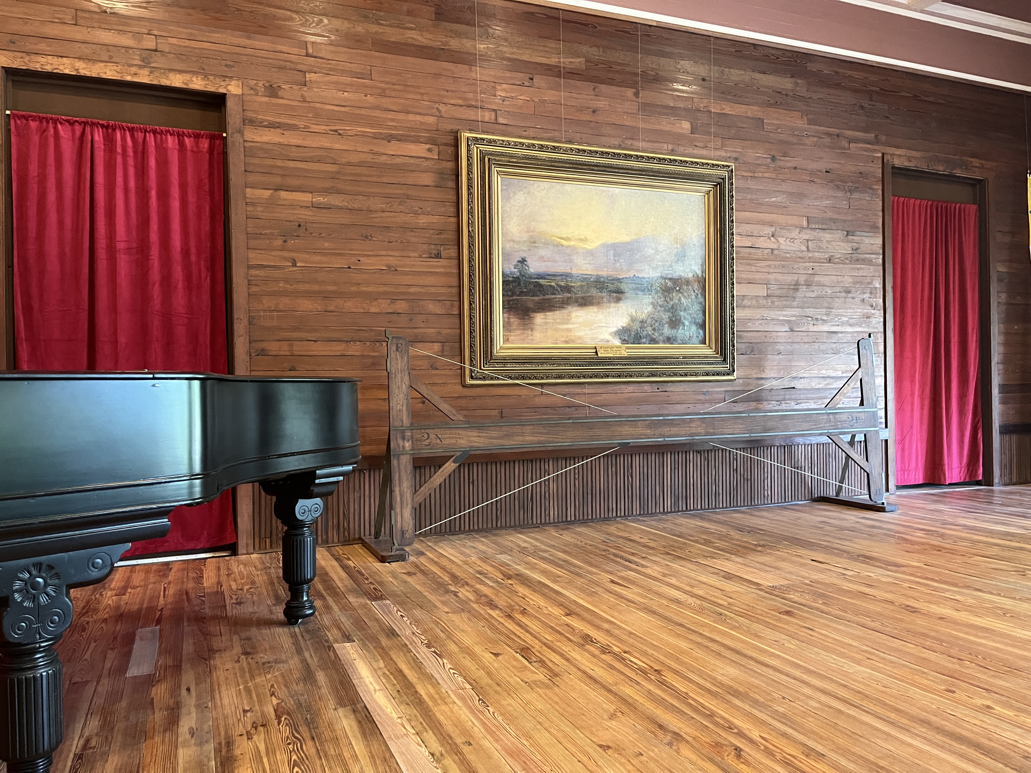
So, the only flaw in this experiment is that it's over 100 years old and has never been publicly repeated since (for obvious reasons), meaning that while the experiment may not be 100% conclusive, it's pretty damn close. Does the Rectilinearizer show that the Earth is concave and we live on its interior surface? It's 99% likely. Unfortunately, the brilliant researcher Steven Christopher Ciummo and his team failed to replicate this experiment on South Padre Island, Texas (February 2016), as they inexplicably forgot to install the guy wires to prevent the girder from collapsing . If a faithful reproduction of the experiment yielded the same results, we could increase this percentage to a 100% probability that the Earth is concave.
Watch Video At: https://youtu.be/YCwBArEldGY
It can also be checked by extending the horizon on its vertical axis with respect to our position, with a sufficiently powerful zoom camera, such as the Nokia P900
Fountain:
http://www.wildheretic.com/concave-earth-theory/6/
References:
https://www.lockhaven.edu/~dsimanek/hollow/morrow.htm
- --
Part 2:
https://creatumejortu.com/la-tierra-es-concava-ii-las-plomadas-de-las-minas-tamarack
Part 3:
https://creatumejortu.com/la-tierra-es-concava-iii-la-tierra-no-se-mueve
Part 4:
https://creatumejortu.com/airys-failure-el-fallo-de-airy
Part 5:
https://creatumejortu.com/tierra-concava-v-la-luz-se-curva
Part 6:
https://creatumejortu.com/tierra-concava-vi-la-imposible-tierra-plana
- --
https://creatumejortu.com/memepedia-astronomia
Visits: 369